Axxa can provide you with more information on the meaning of your alarms and will help you diagnose the source of the problem by explaining the meaning of common FANUC alarm codes. Our technicians
Routinely Service the following Fanuc Servo Amplifiers:
FANUC Alpha, Alpha i series & Alpha is series
FANUC AC Digital and Analog
FANUC AC Serial Interface
FANUC AC Series i & S
We provide a fault diagnosis and a one-year warranty on all FANUC servo repairs and all Fanuc Servo purchases; new, refurbished or used.
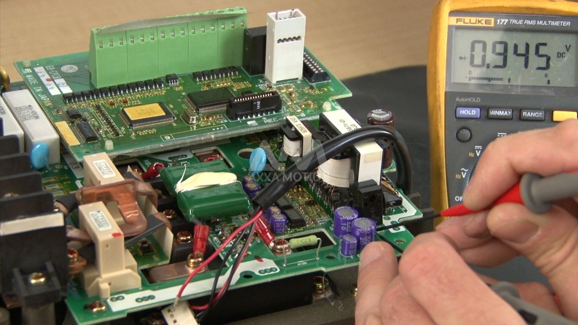
In this blog we will mention the Fanuc Servo Amplifier Alarm Codes and their description.
Alarm Code Description
|
- (dash) |
Amplifier is not ready |
|
Blinking "-" |
(a) Disconnect the feedback cable (JF*) from the Servo Amplifier, and then switch on the power. <1> If blinking continues → Replace the Servo Amplifier. <2> If blinking stops → Go to (b). (b) Disconnect the feedback cable (JF*) from the Pulsecoder, and then switch on the power. (Keep the cable on the Servo Amplifier side connected.) <1> If blinking continues → Replace the cable. <2> If blinking stops → Replace the motor. |
|
0 |
Amplifier is ready (normal operating state) |
|
01, 1 |
DC voltage of the main circuit power supply is abnormally high. Internal cooling circuit faulty Overcurrent flowed into the input of the main circuit. Input supply voltage imbalance, IGBT defective. (PSM-15 to PSM-55) The battery voltage of the absolute pulse coder is low. (warning) The main circuit power module (IPM) has detected an overload, overcurrent, or control supply voltage decrease, overcurrent, or control supply voltage decrease. Internal cooling circuit failure, Overload, Input supply voltage imbalance, IPM failure, or control supply voltage decrease of the power module. |
|
02, 2 |
Internal cooling circuit faulty. Inverter: control power supply undervoltage The battery voltage of the absolute pulse coder is low. |
|
2. (dot) |
+5 VDC of the control circuit power supply is abnormally low. |
|
03, 3 |
DC voltage of the main circuit power supply is abnormally low or the circuit breaker is tripped. The motor has overheated (OHAL). The temperature of the heat sink has risen. |
|
04, 4 |
DC voltage (DC link) has dropped Regenerative discharge energy is too high. –The regenerative discharge circuit is abnormal. Servo motor has overheated (estimated value). |
|
05, 5 |
Average regenerative discharge energy is too high (too frequent acceleration/deceleration) –The transformer overheats. Inverter: DC link undervoltage The input power supply is abnormal (open phase) or the main circuit capacitor was not recharged within the specified time. |
|
5, S |
A communication error for the serial pulse coder was detected. |
|
5. (dot) |
Excessive regenerative discharge alarm. |
|
06, 6 |
Inverter: overheat Soft phase alarm The input power supply is abnormal (open phase). |
|
6. (dot) |
Inverter: overheat |
|
07, 7 |
MCC is faulty. Relay contacts for the dynamic brake is faulty. The DC link voltage is abnormally high. |
|
08, 8 |
Abnormal current alarm (L axis) The offset of the current detection circuit of the main circuit DC link is excessive. The regenerative discharge unit is heated. |
|
8. (dot) |
Inverter: IPM alarm (L axis) |
|
09, 9 |
Abnormal current alarm (M axis) Reference position setting cannot be executed correctly. |
|
9. (dot) |
Inverter: IPM alarm (M axis) |
|
11 |
When the absolute pulse coder is used, the motor has not yet rotated through more than one turn after the first power–up. |
|
16 |
The main circuit power supply has an open phase. |
| 17 |
The DC link voltage is abnormally high. |
| 18 |
An error occurred in internal parameter data transfer processing. |
| 26 |
The frequency of the main circuit input power supply is abnormal. |
| 36 |
The input power supply of the main circuit has an imbalance. |
| 46 |
When the magnetic contactor is turned on, the phase sequence of the power supply cannot be determined. |
| A |
A parameter has been specified incorrectly. Abnormal current alarm (N axis) External cooling circuit is faulty. |
|
A. (dot) |
Inverter: IPM alarm (N axis) |
|
A0 |
ROM is faulty. |
| A1 |
RAM is faulty |
| A2 |
software is not operating normally. |
| b |
Abnormal current alarm (L axis) Abnormally high current in the L–and M–axis motors DC link current alarm (L axis) |
|
b. (dot) |
IPM alarm for L–and M–axis axes. |
|
BRK |
Breaker has tripped |
| c |
An overcurrent alarm or IPM alarm DC link current alarm (M axis) |
| C |
Faulty cooling circuit |
| d |
Abnormal current alarm (N axis) DC link current alarm N axis) |
| DC |
Discharge alarm |
| DCAL |
The regenerative discharge circuit may be faulty |
| E |
An error was detected in the RAM write/read test at power–up. The input power supply is abnormal (open phase). |
| F |
External cooling circuit faulty |
| H |
The temperature of the regenerative resistor has arisen abnormally. (PSMR) |
|
HCAL L/M |
High current flow the main circuit of that axis has occurred |
|
HCL |
High current alarm L axis |
|
HCM |
High current alarm M axis |
|
HV |
High voltage alarm |
|
HVAL L/M |
DC voltage of the power circuit for that axis is high |
| J |
The regenerative discharge unit has overheated |
| L |
FSSB communication error |
| LV |
Low voltage alarm |
|
LVAL |
The circuit voltage is unusually low |
|
No LED |
200-V control power (CX1A) is not supplied. Alternatively, the 24-VDC power is short-circuited. |
|
OH |
Overheat alarm |
|
OVC L/M |
Current exceeding the preset value has continued longer than normal. |
| P |
Communication error between amplifier and module DC link low voltage alarm |
|
TGLS L/M |
Feedback and velocity command mismatch |
| U |
A parameter that requires power–down has been specified. FSSB communication error |
| u |
A first to third reference position return cannot be executed because the reference position has not yet been established. |
| Y |
DC link overvoltage alarm |
SERVO CORE EXCHANGE PROGRAM AND FANUC REPAIRS
Send your damaged/faulty Fanuc units to Axxa and our team of experienced and highly skilled repair technicians will evaluate and determine what repairs, if necessary to bring the unit to a reliable working condition. If the repairs are time sensitive and its taking too long for the repair or you can’t wait around for a repair, we can give you a replacement unit from our exchange stock. All exchange and repaired FANUC assemblies ship with a one-year warranty. All Fanuc repairs are done in house at Axxa.
Fanuc units we service (Sales and Repairs) Include:
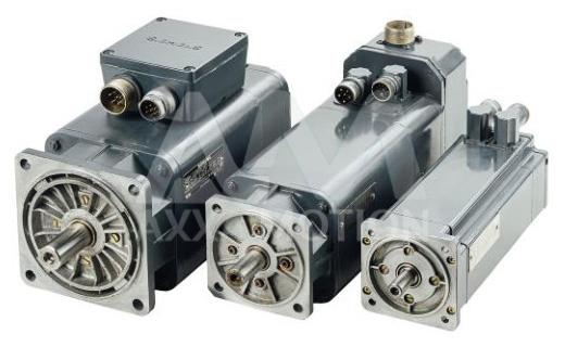
FANUC Servo & Spindle Drives
FANUC Servo & Spindle Motors
Servo & Spindle Amplifier Modules
FANUC Power Supplies
PCBs for FANUC CNC Controls (System 3, 5, 6, 10, 11, 12 and Series 0, 16, 18, 21, & 15)
FANUC Robot Parts
Please contact us or call us at (716) 270-0047. We offer No Bench Fee evaluations and all repairs are complemented by our unique ‘No Fix No Fee’ promise. Axxa offers competitive repair pricing, quick turnaround and a reliable and tested Fanuc replacement unit, if needed, from our exchange stock.